CIVIL WORKS GUIDELINES FOR MICRO-HYDROPOWER IN NEPAL
103
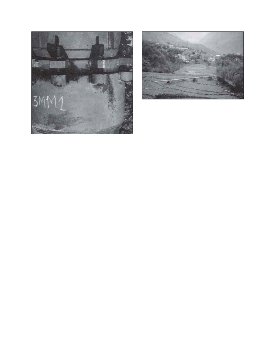
Photo 6.14 Penstock at Ghandruk with village in the background
Photo 6.13 Sliding expansion joint, Jhankre mini-hydro
The following coats of paint are recommended:
Outside surface of above ground mild steel pipes
First two coats of primer should be applied on the pipe surface.
Red Oxide Zinc Chromate primer is appropriate for this purpose.
Then another two coats of high quality polyurethane enamel
paint should be applied on top of the primer.
Outside surface pipe of which will be buried or cast into
anchor blocks
Two coats of primer similar to above ground pipe should be
applied. Then, another two coats of high-build bituminous
paint should be applied over the primer. Provide an extra coat
of bituminous paint at transition areas, which are more prone
to corrosion (see Figure 7.1).
Inside surface of pipes
For small diameter pipes it may not be possible to paint the
inside surface. However whenever possible, the inside surface
should be painted with two coats of good quality red lead
primer. If there is a doubt about the quality of paint, the
supplier’s specifications should be checked prior to its use.
Note that paintwork is not required for HDPE or PVC pipes.
Any paintwork damaged during transport and installation
must be made good, so that the full number of coats is present
everywhere. This is especially important for buried pipes.
6.12 Installation
The following procedure should be used:
The centreline of the penstock should be set out using a
cord and pegs along the selected route as shown in Figure
6.8. For micro-hydro schemes above 20 kW of installed
capacity, a theodolite should also be used to ensure that
the bend angles correspond to the fabricated pipe bends.
A line should be marked by spreading lime on the surface
of the ground to replace the cord. Then the positions of
anchor blocks and support piers should be marked to the
required spacing for exposed pipes and excavation carried
out along this line as required.
For buried pipes, the penstock is installed in the excavated
trench and backfilled as shown in Figure 4.8. The backfill
should be rammed in layers and a slight hump above the
level of the ground helps to keep the alignment dry. An
improperly backfilled penstock alignment can quickly become
the route for drainage water down the hillside. However,
note that backfill should be completed only after the pipe
has been pressure tested.
For exposed pipes, the anchors and supports should be
constructed as will be discussed in Chapter 7. The pipe
should be cast into the anchors and placed on one support
pier at a time. No further supports or anchors should be
built until the pipe is secured to the previous anchor block
or support pier. For both site welded and flange connected
pipes, the end should protrude from the last support block
with adequate margin (~ 300 mm) so that either the flange
or the weld line does not lie on the support pier during
thermal expansion or contraction. If more than one pipe
section needs to be welded between the support piers,
temporary supports should be used as shown in Photograph
6.15. Flange connected pipes should be joined and the
bolts tightened as the installation progresses.
The installation of the penstock should start from the
machine foundation and proceed upstream. This avoids
any misalignment between the penstock and the turbine
housing. Since the turbine needs to be firmly fixed to
the machine foundation, there is almost no tolerance at
this end after the machine foundation has been
constructed. Furthermore, the pipe sections below the
expansion joints can slide down if installation proceeds
downstream from the forebay. Minor pipe deviation can
be adjusted at the forebay wall, but such adjustment is